Filtration
Introduction
For anybody wanting to set up a sump system, I would consider Greg Taylor's series of three articles an absolute must-read. In addition, if you care at all how much noise your setup makes - and it can make a lot of noise if you don't prevent it from doing so - you can't go past Richard Durso's excellent web site on standpipes. He sells them, but also has plenty of information if you want to build your own. Use the inconspicuous looking blue banner at the top for navigation. The site contains a wealth of information. The system I build was very much modeled on a system Brad Newton (a.k.a. Featherfinfan on Cichlid-forum) had set up. Brad never tired of answering my emails about details of his setup, and supplied pictures and detailed instructions about what he had done. Many thanks, Brad, for sharing your wealth of experiences! 240G of water on the floor was not a scenario I ever wanted to face, plus I expected to house some hard to replace fish in the tank in the long term. For this reason, I decided to redundantly engineer the filtration system of this tank. This means that all parts have been duplicated, and in case one side of the filtration system fails, the other will be able to take over completely. In addition, everything has been dimensioned so that if one side of the filtration system has to maintain the tank by itself, it should be able to do so for a prolonged period of time without being at the limit of its capability. If, for example, I went on holiday and the largest fish in the tank died and completely blocked one of the overflows, I am pretty confident that the system would continue to run until I returned a couple of weeks later without missing a beat. In addition I believe that the biofiltration I have, in conjunction with the automatic water changer and the large system volume, would be able to cope with the added bioload from the decaying fish without creating a critical condition for the rest of the tank inhabitants. I haven't actually checked if this is really true, and I don't hope it will ever come to that, but it's nice for a large tank like this to have this peace of mind.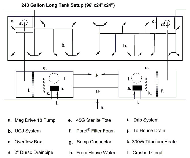 Schematic diagram of the plumbing of my 240G Lake Tanganyika community setup. If you have trouble reading the text, please click on the diagram and a larger version will open in a new window. Then position both windows so that you can see the diagram while taking my tour through the plumbing system.
To understand how the plumbing of this tank works, let's just imagine we are one drop of water, and make the journey through the system. We are going to start at the piece of equipment that sets it all in motion, the pump (a.). My pumps are fully submerged in the sumps, from where they pick up the water and deliver it through ¾" PVC hose over the back wall of tank to a 9-jet and 12 jet under gravel jet (UGJ) system (b.), respectively. The UGJ systems disperse the water throughout the tank, and help to prevent any debris from settling on the ground, but keep it in motion and wash it into the overflow boxes (c.). From there the water runs into 2" modified Durso drainpipes (d.). In these pipes air is mixed with the water providing superb aeration to the whole system. From the drainpipes the water runs into 45G Sterilite Totes (e.) that serve as sump containers. Each sump containers is divided by a sheet of Poret® Filter Foam (f.), through which the water has to pass before it is picked up again by the pump. The Poret® Filter Foam takes care of mechanical as well as biological filtration. Since it is technically impossible to ensure that the overflow box on each side picks up the exact amount of water that it's corresponding pump transports into the tank, the two sumps have to be connected (g.) in order to allow their water levels to balance out.
An additional plumbing features of this tank is its continuous automatic water change (CAWC) system (h, i, j). Last but not least, the sumps also house one 200W Titanium heater each (k.) and a strainer full of crushed coral (l.), which acts as additional biofilter material and at the same time leaches minerals in the water, which bring it closer to rift lake conditions.
To give you a better impression on how it was all put together, here are two views into the cabinet under the tank before most of the stuff went in there. Now it's so full that you can't see a thing.
Schematic diagram of the plumbing of my 240G Lake Tanganyika community setup. If you have trouble reading the text, please click on the diagram and a larger version will open in a new window. Then position both windows so that you can see the diagram while taking my tour through the plumbing system.
To understand how the plumbing of this tank works, let's just imagine we are one drop of water, and make the journey through the system. We are going to start at the piece of equipment that sets it all in motion, the pump (a.). My pumps are fully submerged in the sumps, from where they pick up the water and deliver it through ¾" PVC hose over the back wall of tank to a 9-jet and 12 jet under gravel jet (UGJ) system (b.), respectively. The UGJ systems disperse the water throughout the tank, and help to prevent any debris from settling on the ground, but keep it in motion and wash it into the overflow boxes (c.). From there the water runs into 2" modified Durso drainpipes (d.). In these pipes air is mixed with the water providing superb aeration to the whole system. From the drainpipes the water runs into 45G Sterilite Totes (e.) that serve as sump containers. Each sump containers is divided by a sheet of Poret® Filter Foam (f.), through which the water has to pass before it is picked up again by the pump. The Poret® Filter Foam takes care of mechanical as well as biological filtration. Since it is technically impossible to ensure that the overflow box on each side picks up the exact amount of water that it's corresponding pump transports into the tank, the two sumps have to be connected (g.) in order to allow their water levels to balance out.
An additional plumbing features of this tank is its continuous automatic water change (CAWC) system (h, i, j). Last but not least, the sumps also house one 200W Titanium heater each (k.) and a strainer full of crushed coral (l.), which acts as additional biofilter material and at the same time leaches minerals in the water, which bring it closer to rift lake conditions.
To give you a better impression on how it was all put together, here are two views into the cabinet under the tank before most of the stuff went in there. Now it's so full that you can't see a thing.
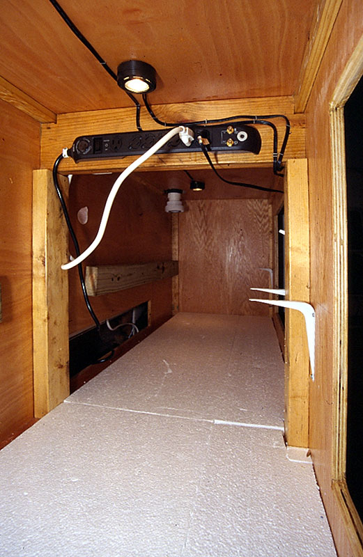 Inside the right-hand side of the stand. You can see the cabinet lighting (top) and electric outlets, which have been installed high to prevent short outs and electrical fires in case of flooding. The white L-brackets on the right hold the 2x4 supports for the sump containers in place. The bottom of the stand is covered with Styrofoam to prevent long term stress and cracking of the sump containers. In the very back you can see a 2" union, to which the lower part of the drain pipe will be attached. In the back on the left, you can see that the backwall of the cabinet is open so that the ducted heating of the house can circulate air through the cabinet. The pipes for the continuous automatic water change system will also be fed through that hole.
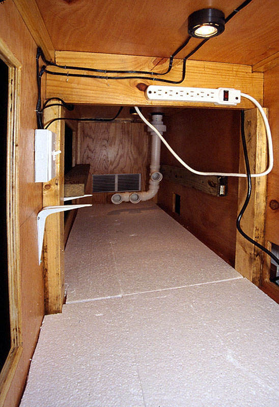 Inside the left-hand side of the stand. You can see the cabinet lighting (top) and the corresponding light switch (left). The white L-brackets on the left hold the 2x4 supports for the sump containers in place. The support for the sump in the back is installed, as is the drainpipe including the manifold to hold three The micron filter bags (a part of the filtration system that has now been replaced by Poret® Filter Foam). The bottom of the stand is covered with Styrofoam to prevent long term stress and cracking of the sump containers.
Leave a Reply
You must be logged in to post a comment.
